

Overview
Iris for NASA
Helping rocket engineers align their design assumptions
Jan 2019 – August 2019
NASA Internship for MHCI Capstone
Team Project // 5 people
Problem
It’s hard to coordinate rocket design.
Currently, NASA is designing and building the SLS (space launch system), a new rocket with planned missions to carry astronauts around the moon and later to Mars. NASA is on a strict schedule, but delays are common because it is difficult for engineers to coordinate their rocket design activities on such an expansive and complex project. Engineers are handed requirements to guide their work, but they often unknowingly interpret and verify these requirements in incompatible ways. This leads to costly schedule delays, rework, and overall demoralization of teams.
Solution
Iris, the collaborative tool to align design assumptions.
Iris is a collaborative web application that gives engineering teams a window into the work other teams are doing, enabling them to efficiently resolve concerns and understand how their work relates to that of other teams. This tool helps disparate engineering teams align on the design work they are doing, ultimately reducing rework and and helping programs like the SLS launch successfully and on schedule.
Follow our journey on Medium!
Methods
Concept Mapping, Interviews, Affinity Diagramming, Journey Mapping, Sequence Modeling, Speed Dating, Paper Prototyping, Stakeholder Walkthroughs, Think-Alouds
Tools
Figma, Sketch, Principle, Illustrator, HTML/CSS/Javascript
Role
I served as a Lead UX Designer on the team, contributing mainly to concept/feature definition and UI design.

Background
PROJECT ROADMAP

“Building the SLS is one of the most complex engineering projects ever undertaken by man.”
PROJECT CONTEXT
A brief introduction to rocket design at NASA
Team “Far Out”, my amazing capstone group

Designing the most powerful rocket
NASA engineers are currently working to design and build the Space Launch System (SLS), the most powerful rocket ever made, with plans to launch in 2020. But as you may have guessed, rocket design is a complex business and delays are common. Each system (such as the main booster) is made up of many subsystems, which are in turn made up of smaller subsystems, each of which affects the other. Level 3 discipline engineers work on teams to design these subsystems.
All the different levels of system development must be tracked and coordinated across level 3 teams in order for the final rocket design to be successfully completed. For this reason, it is hard to get rocket designs to “done.”

Managing the design process through requirements
Each system that makes up the rocket must fulfill certain requirements. Requirements are specifications that detail what each part should be able to accomplish.
There are two types of requirements: functional and performance. A functional requirement defines what an element or subelement should do (e.g. “the rocket must be able to lift payload into orbit”). A performance requirement gives numerical parameters for verification activities (e.g. “ 154,000 pounds of payload +-500 pounds into orbit”).
Four or five discipline teams may be working off of the same requirement to design their part of the rocket. Every couple months, teams undergo milestone reviews. These reviews are periodic checkpoints in the rocket design process where teams come together to evaluate work they have done to verify their requirements and ensure all the subsystems integrate. It is often only at these milestone reviews that teams discover that they have been verifying and interpreting the same performance requirement in incompatible ways, causing them to go back and re-work their designs.
Our Task
Myself, along with 4 other students in Carnegie Mellon’s Master of Human Computer Interaction Program, were given the following initial problem statement: “create a tool that helps engineers get rocket designs to ‘done’ more efficiently.” As interns of NASA, we worked to scope this problem and develop an innovative solution to streamline the rocket-design process.
Final Design
Refined Prototype
PRODUCT OVERVIEW
Iris for NASA

What is Iris?
A collaborative software tool for level 3 rocket engineers at NASA.
Iris web application designed to assist level 3 discipline engineers in designing their newest rocket, the Space Launch System (SLS). This tool helps them align their design assumptions—specifically, their interpretations and verifications of performance requirements. By simplifying complex data, Iris enables these engineers to understand the way other teams are working with these requirements, encouraging communication and collaborative problem-solving to break down discipline silos.
To understand our process in arriving at this solution, visit our project website here.


Key Features
Why Iris?
Because coordinating rocket design is a complex task.
Through generative and evaluative research, we discovered that when level 3 discipline teams sync during milestone reviews to ensure all subsystems will integrate, they frequently discover misalignments regarding how a requirement has been interpreted and used. This issue is the result of a lack of transparency across teams, unstructured communication, and lost decision points in a complex, decentralized information environment. The consequences include costly schedule delays and overall demoralization.
Iris encourages greater transparency of information across teams and provides facilitation and documentation around communication— all while centralizing data for easy access and usage. Ultimately, Iris aligns engineers on their design work, helping them finish the rocket schedule.
PRODUCT WALKTHROUGH
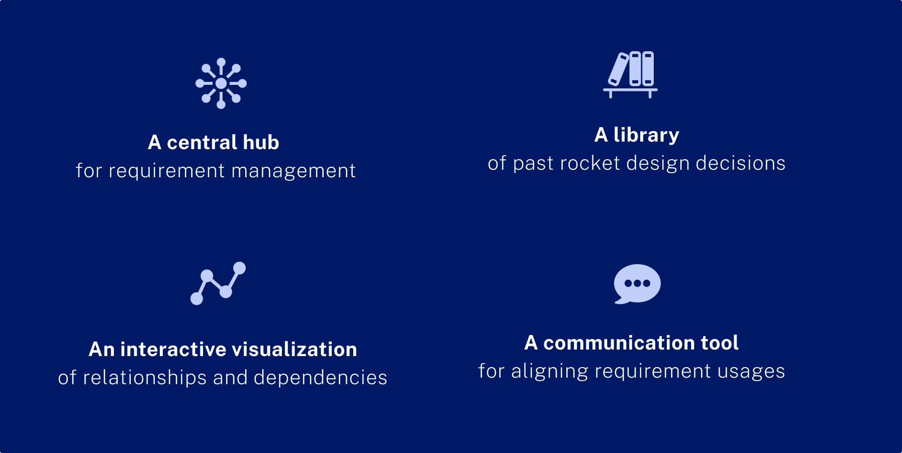
A central hub for requirement management
1. Home Page

REQUIREMENT DASHBOARD
Summary: The homepage serves as a central hub for level 3 discipline engineers to access the requirements they need to complete their work.
If they expand the requirement by clicking “view details”, engineers can see a preview of how other teams are verifying the same requirement. If there is a notification on a particular requirement, the details are expanded automatically.
Rationale: This page enables engineers to quickly get an overview of their current requirement work and understand how other teams are interpreting the same requirement. This not only helps for project management (engineers currently use spreadsheets to manage requirements), but also helps them align with other teams, avoiding costly rework later down the line.
DESIGN SPOTLIGHT


2. Requirement Page

A LOOK INTO REQUIREMENT DETAILS
Summary: In engineers click into a specific requirement from the homepage, they land here. On this page, engineers can see all other teams’ “Usage Contexts”— the verification activities they have chosen for this particular requirement and why. If there are unread discussion activities on a particular Usage Context, a red dot appears next to “View Discussion” on the card.
Engineers are also provided a quick view of “Relationships” —how data flows across documents and how teams are related to one another.
Rationale: Seeing everything in one place reminds engineers that their work is a part of a larger system, and it takes collaboration across teams to complete the “bigger picture.” We prioritize key information to display, prompting them to click into each section if they want more details.
DESIGN SPOTLIGHT

A communication tool for aligning requirement usages
1. Usage Context Details Page

COMMENTING ON TEAMS’ CONTEXTS
Summary: Selecting a team’s Usage Context card lands the user here. Designated discussion space on each teams’ Usage Context provides a public space for aligning design assumptions. When a decision has been reached on a discussion post, the original poster can mark a resolution point from any of the post comments. This resolution will be pushed to the top of the post thread as a highlight alongside the originating post, creating a reference point for other users trying to understand the conversation around usage of a particular requirement.
Rationale: We created this discussion feature to encourage cross-team communication early and often to catch discrepancies prior to milestone reviews. By capturing resolution points, we solve the problem of undocumented decisions.
.
DESIGN SPOTLIGHT


2. Request for More Information (RFI) Form

A MORE PRIVATE, FORMAL STRUCTURED COMMUNICATION METHOD
Summary: When a public comment can’t capture sufficient granularity or offer the privacy needed for sensitive data, Requests for Information (RFIs) fill the need. RFIs allow engineers to more formally request documentation or information outside the scope of a casual comment. RFIs can later be archived and referenced to inform future designs.
Once an RFI is sent, the conversation can be continued in-app so data can be contained in one place.
Rationale: Data security is a big challenge at NASA; not everyone has access to everything, and engineers can be protective over their documents. The RFI allows engineers to share data in a more private, secure fashion while avoiding the messiness that comes with email.
A library of past design decisions
1. Version History Modal

TRACKING DECISIONS + THE DISCUSSIONS THAT LEAD TO THEM
Summary: From the Usage Context Details Page, users can access the Version History Modal. Here, engineers are able understand how a team’s Usage Content has evolved over time. They can also see “attached posts” — the comment conversations that lead to a particular change. In this way, engineers understand the context for each version.
Rationale: NASA makes history, and history makes NASA. Level 3 engineers often use past decision-making to help guide their current designs. Historical references can come from decisions made decades ago in past programs, such as Space Shuttle, or just decisions made a few months ago. Regardless, creating a documentation trail of historical decisions is essential. We created the Version History functionality to answer this need and facilitate decision traceability.
DESIGN SPOTLIGHT

An interactive visualization of relationships and dependencies
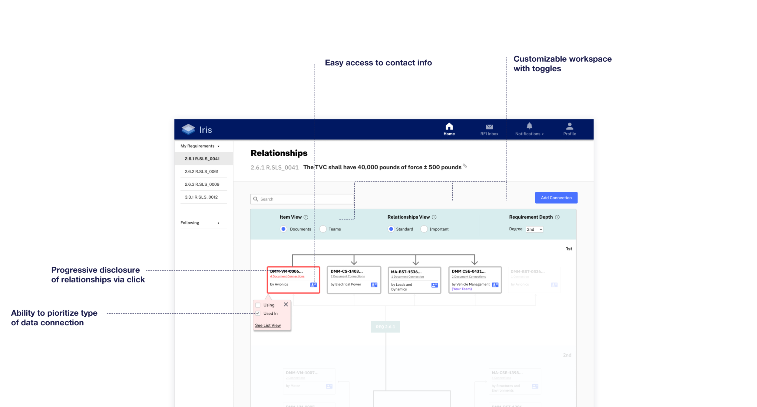
1. Relationships Diagram

A FLEXIBLE WAY TO UNDERSTAND THE SLS ECOSYSTEM
Summary: A visualization of the relationships between requirements, documents, and teams gives engineers a broad perspective of what’s happening across SLS development. We surface critical information that supports engineers in designing subsystems that can integrate successfully, helping align design assumptions and communicate with relevant teams.
Engineers have flexibility to choose the view that best suits them; they can prioritize Teams versus Documents, Standard versus Important relationships, select the degree of Depth in Requirement relationships.
Rationale: An engineer’s needs evolve as the project evolves. Earlier in the program when requirement decisions are in flux, it’s important to understand the larger discipline team ecosystem around you. Later in the program, it’s more important to have an understanding of how models are being used to fulfill documents and what connections are most important.
VIEWING DATA CONNECTIONS
Summary: If engineers click into a particular verification document, they see how that document is connected to other documents. The outward arrows indicate that data is flowing outward from that document into other documents (ie data is being used from that document), while the inward indicate that data is flowing inward from other documents (ie that document is using data from other documents). This enables engineers to understand how data in their document in being used, as well as what data from other documents they are using in their own.
Rationale: It is extremely important for engineers to keep track of how their data is being used. In our research, we heard time and time again that data is often used in contexts it wasn’t meant for. Further, it is often difficult to trace where data originated, as conversations are often lost within email threads. We created this visualization so engineers could track how documents interface with one another, ensuring everybody is aligned on design decisions and using each other’s data correctly.

DESIGN SPOTLIGHT

2. Relationships List View

AN ALTERNATIVE WAY TO VIEW DOCUMENT CONNECTIONS
Summary: In addition to monitoring document connections visually in the Relationship Diagram, engineers can also easily access a list view of document connections.
Rationale: This gives engineers a clear, consolidated way to understand how the data in their documents is being used. Additionally, if they don’t like visual representations of connections provided in diagram, they can come here.
IMPLEMENTATION
We worked with a front end developer to code out a key flow that we thought best communicated the core value of Iris. The video you see below is a screen capture of a functional web app coded using HTML, CSS, and Javascript.

REFLECTION
What I Learned
Ask clarifying questions if there is any ambiguity. Often, our users would make a statement that was somewhat ambiguous to us, and each of the team members in the interview would interpret the statement differently because we weren’t all that familiar with rocket science. To fix this issue, we learned to always ask clarifying questions to get to the root of the statement and ensure we were properly aligned. Once we started doing this, we were able to synchronize our interpretations and get much more specific, targeted feedback that we could turn into actionable insights.
Always document decisions. Often, my team had lengthy discussions about certain details of our complex problem space. We would finally arrive at a decision, only to forget the decision days later and have to re-align. To solve this problem, we learned to always write down our decision points and rationale so we could easily reference them after and say on track.
Find low effort, easy ways to get feedback from users. Because our users were extremely busy and located hundreds of miles away from us, we had to get creative about how and when we tested our prototypes. We learned to use low effort, quick ways of eliciting feedback like storyboarding and email responses. We also learned to prioritize different types of testing--for example, we tested our prototypes with NASA engineers when we wanted to validate usefulness or our concept and features. However, to test usability, we tested our prototypes with members of the HCI group at Ames.
Choose fidelity of prototypes carefully. As rocket engineers, our users were very concrete and numbers-focused. When attempting to glean information about overall usefulness of concepts, we often got unwanted feedback about data being unrealistic. We learned to ensure data fidelity was lo-fi enough that users didn’t fixate their attention on it .
